Wiring 2 Three Phase Motors into a Single VFD
WARNING/DISCLAIMER:
The information in this page worked for me, I CANNOT GUARUNTEE THAT IT WILL WORK FOR YOU. THE RESPONSIBLITY FOR CONDUCTING THIS MODIFICATION IS ENTIRELY YOUR RESPONSIBILITY. I ASSUME NO RESPONSIBLITY OF LIABILITY SHOULD YOU HAVE ISSUES OR DESTROY YOU VFD, MOTORS, OR OTHER EQUIPMENT IF YOU ATTEMPT THIS MODIFICATION
READ "NOTES" AT THE BOTTOM OF THE PAGE FOR ADDITIONAL WARNINGS.
Materials you will need
I am assuming that you already have at least one VFD of the proper capacity, and two of the appropriate 3 phase motors that you wish to wire into a single VFD.
I assume that as long as the VFD you use has the capacity for the largest motor you're using, then it SHOULD be OK to wire in a second motor of equal/lesser Hp/power requirements, HOWEVER I DO NOT KNOW THAT FOR SURE....ONCE AGAIN, YOU'VE BEEN WARNED! OK, now that you know this is all ON YOU, let's proceed.
-This toggle switchhttps://www.surpluscenter.com/Electrical/Switches/Toggle-Switches/DPDT-CO-Toggle-Switch-20-Amps-66-1806-11-3220.axd
(This modification only requires a 9 pole toggle switch, but I could not source one of those at the time, so I used a 12 pole)
-14-4S Wire (14 gauge/4 conductor/stranded wire).... Enough to make the connections from the toggle switch inside the VFD to each motor.
-Crimp on connectors (I used the crimp on conectors with a hole in them to ensure a tight fit to the toggle switch poles/screws)
-Wire nuts for wiring motor wires to 14-4s wire
-any "glands" needed to protect the wires going in/out of the VFD housing, and into the motor wiring box(es)
Wiring Diagram
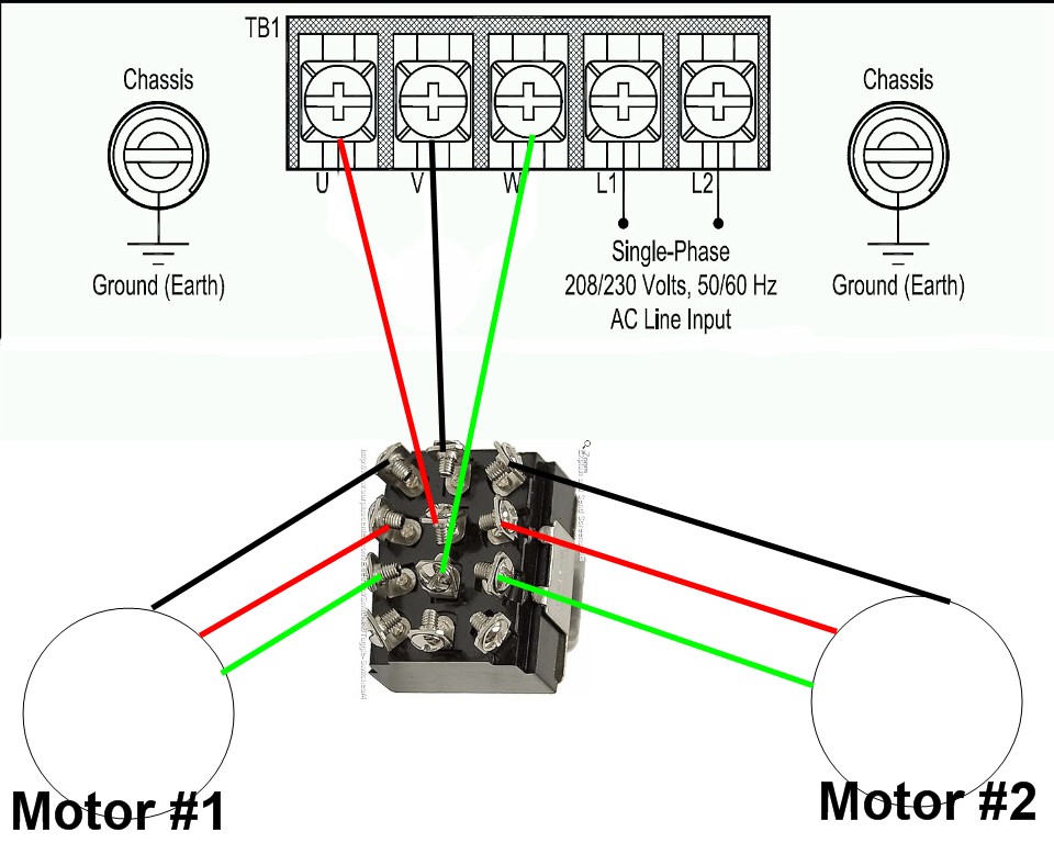
In the above image, the L1 & L2 are the single phase 220V input (ensure you also hook the ground wire to the terminal on the VFD chassis.
U,V, & W are the terminals that output power FROM the VFD to the motor. In this case those three wires (red, black, and green) are wired to 3 poles in the CENTER of the toggle switch. This provides power to the toggle switch. I then wired the same color wires from the terminals on one side of the toggle switch to one motor, and did the same from the other side of the toggle switch poles, to the remaining motor. (you must also run a ground wire from each motor to the ground lug on the inside of the VFD chassis, this is NOT pictured in the diagram) Since I already had the VFD hooked to a single motor (before I wired two motors to a single VFD), I labeled each of the wires as they connected to the motor, and ensured I did the same colored wires to the same terminals/motor wires. If you happen to get a wire out of place, GENERALLY all that will happen is that the motor will run the wrong direction/rotation. If this happen, simply switch around two of the wires inside the motor wiring box (the wiring box that is mounted to the actual motor) and it should rotate the correct way.
U,V, & W are the terminals that output power FROM the VFD to the motor. In this case those three wires (red, black, and green) are wired to 3 poles in the CENTER of the toggle switch. This provides power to the toggle switch. I then wired the same color wires from the terminals on one side of the toggle switch to one motor, and did the same from the other side of the toggle switch poles, to the remaining motor. (you must also run a ground wire from each motor to the ground lug on the inside of the VFD chassis, this is NOT pictured in the diagram) Since I already had the VFD hooked to a single motor (before I wired two motors to a single VFD), I labeled each of the wires as they connected to the motor, and ensured I did the same colored wires to the same terminals/motor wires. If you happen to get a wire out of place, GENERALLY all that will happen is that the motor will run the wrong direction/rotation. If this happen, simply switch around two of the wires inside the motor wiring box (the wiring box that is mounted to the actual motor) and it should rotate the correct way.
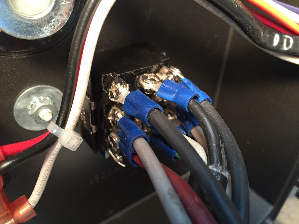
Here are images of what the actual parts & wiring look like, with labels

Power into the VFD from a single phase, 220V source. (the white and black wires are the power/ L1 & L2) The green wire is the ground, ENSURE YOU GROUND TO THE LUG OF THE VFD CHASSIS

The above image shows where I placed the toggle switch into the VFD housing. I had to slightly enlarge the hole in the housing for the toggle switch to fit.


<front and back> views of the toggle switch

What the wiring inside my VFD looks like when completed. I left the exterior insulation on the power wires from the VFD U, V, & W terminals to the center poles on the toggle switch just to make them easier to manage and keep track of.
This is what the back side of the toggle switch looks like once its wired. A total of 9 wires.... 3 wires on the middle row of poles go to U, V, & W terminals on the inside of the VFD. 3 wires on the left row of terminals go out to one motor, and the 3 wires on the right row of terminals go to the other motor.
Notes...Read All of These!
-IF YOU ARE NOT COMPETENT OR COMFORTABLE WITH ELECTRICAL WIRING, DO NOT ATTEMPT THESE MODIFICATIONS! FIND/USE A QUALIFIED ELECTRICIAN.
- ALL OF THE INFORMATION IN THIS PAGE IS BASED ON MY OWN EXPERIENCES. I AM NOT AN ELECTRICIAN. YOU ASSUME ALL RESPONSIBILITY/RISK FOR ATTEMPTING THESE MODIFICATIONS, AND FOR ANY EQUIPMENT/PARTS THAT ARE DAMAGED OR DESTROYED.
-THIS MODIFICATION WORKED FOR ME, HOWEVER I CANNOT GURANTEE THAT IT WILL WORK FOR YOU.
- OUTSIDE OF THE INFORMATION PRESENTED HERE, I LIKELY CANNOT HELP YOU WITH ANY QUESTIONS IF YOUR SETUP/VFD/MOTORS IS/ARE DIFFERNET FROM WHAT I'VE PRESENTED ON THIS PAGE.
-I KNOW THIS MODIFICATION WILL WORK FOR TWO IDENTICAL MOTORS BEING WIRED INTO A SINGLE VFD (IN MY CASE A KBAC-29D CONTROLLER AND TWO LEESON 3HP/3 PHASE MOTORS), I WOULD ASSUME, BUT DO NOT KNOW FOR SURE IF IT WILL WORK WITH MOTORS OF DIFFERNT HP RATINGS.
-IF YOU ATTEMPT THESE MODIFICATIONS, IT IS UP TO YOU TO ENSURE YOU USE THE CORRECT WIRING, PARTS, MOTOR(S), AND VFD FOR YOUR INTENDED APPLICATION(S). USING INCORRECTLY RATED PARTS CAN RESULT IN DAMAGED/DESTROYED EQUIPMENT, OR POSSIBLE ELECTRICAL FIRES......ONCE AGAIN, YOU'VE BEEN WARNED!
-WHEN SWITCHING POWER FROM ONE MOTOR TO THE OTHER, IT IS ESSENTIAL THAT YOU WAIT UNTIL ONE MOTOR COMPLETELY STOPS, BEFORE SWITCHING POWER TO THE TO THE OTHER MOTOR. SWITCHING POWER BEFORE ONE MOTOR COMES TO A COMPLETE STOP MAY DAMAGE/DESTROY THE VFD, AND POSSIBLY DESTROY THE TOGGLE SWITCH. THE BEST WAY TO BE SURE IS TO WATCH FOR THE "ACTIVITY" LIGHT ON THE KBAC CONTROLLER TO TURN ORANGE. ONCE THE LIGHT IS ORANGE, IT'S SAFE TO CHANGE THE TOGGLE SWITCH POSITION.
-WHILE NOT DIRECTLY SPECIFIED, I HIGHLY ENCOURAGE THE USE OF A POWER CUT OFF SWITCH WIRED IN BETWEEN THE VFD AND THE POWER SOURCE. WHEN THE VFD/MOTORS ARE NOT IN USE, ITS ONLY PRUDENT TO CUT THE POWER TO THE VFD.
Many Thanks go out to my best friend Steve Kelly at SK Knives for letting me know about this modification and how he did it.

Two 3hp/3 Phase motors operated from a single KBAC-29D VFD/Controller!


"Nobody Cares What you Know...
Until They Know You Care!"
Until They Know You Care!"
Copyright 2024/25: "The Montana Bladesmith"
406-727-9102